EN
EN
 AR
AR
 CS
CS
 FR
FR
 DE
DE
 IT
IT
 JA
JA
 KO
KO
 PT
PT
 RU
RU
 ES
ES
 ID
ID
 VI
VI
 TH
TH
 TR
TR
 MS
MS

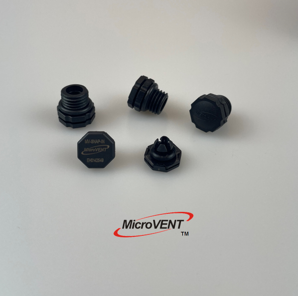
Inverter surya menghasilkan panas signifikan selama operasi, dan pengelolaan beban termal tersebut sangat penting untuk menjaga efisiensi serta umur pakai sistem. Sistem aliran udara MicroVent® bolt dirancang khusus untuk mengatasi tantangan ini dengan menyediakan ventilasi terkendali melalui komponen pengikat yang didesain secara presisi. Mengoptimalkan laju aliran udara MicroVent® bolt secara langsung memengaruhi seberapa efektif inverter surya Anda dalam menghilangkan panas, yang pada gilirannya memengaruhi efisiensi konversi daya, masa pakai komponen, serta keandalan keseluruhan sistem. Memahami cara mengonfigurasi dan merawat aliran udara MicroVent® bolt secara tepat memastikan infrastruktur surya Anda beroperasi pada kinerja puncak.
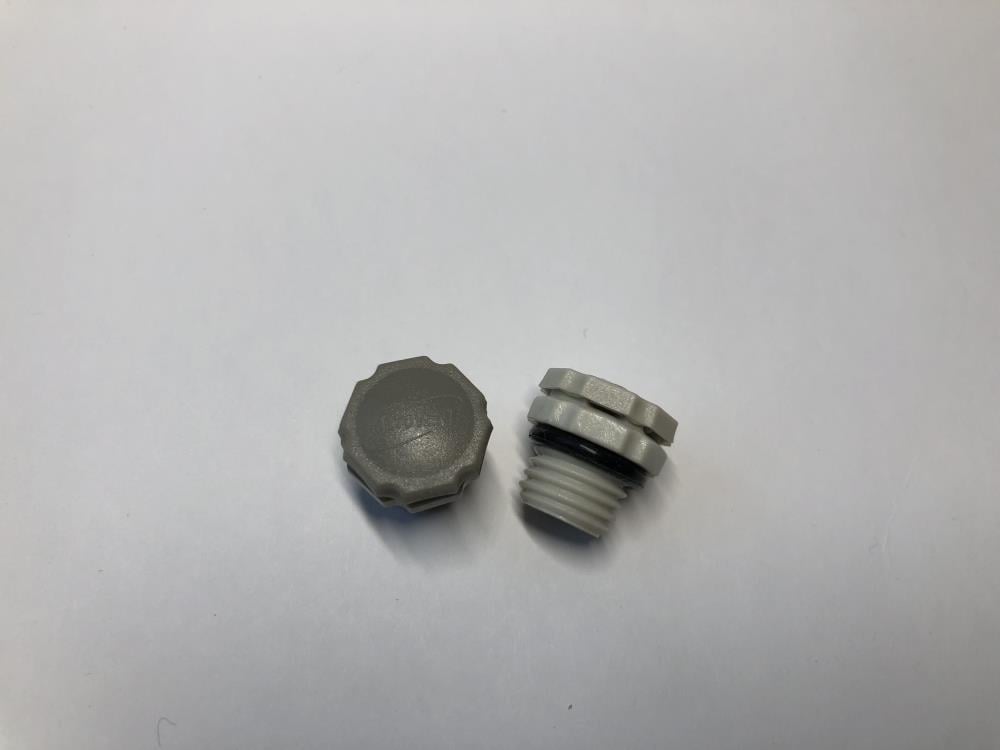
The baut desain aliran udara ini menggabungkan presisi mekanis dengan prinsip rekayasa termal guna menciptakan jalur pendinginan optimal di dalam pelindung inverter surya. Ketika dioptimalkan secara tepat, aliran udara MicroVent® bolt memberikan sirkulasi udara yang konsisten sehingga mencegah titik panas, mengurangi tekanan termal pada semikonduktor, serta menjaga suhu operasi yang stabil di semua kondisi beban. Artikel ini membahas metode praktis untuk mengoptimalkan kinerja aliran udara MicroVent® bolt dalam sistem energi surya Anda.
Memahami Mekanisme Aliran Udara Baut MicroVent®
Cara Kerja Sistem Aliran Udara Baut MicroVent®
Sistem aliran udara baut MicroVent® beroperasi melalui kombinasi konveksi alami dan saluran udara yang dirancang khusus, yang terintegrasi ke dalam struktur baut itu sendiri. Berbeda dengan pendekatan ventilasi konvensional, desain aliran udara baut MicroVent® memanfaatkan geometri fisik komponen pengikat untuk menciptakan jalur berhambatan rendah bagi pergerakan udara termal. Jalur-jalur ini memungkinkan udara panas keluar dari zona berpanas tinggi di dalam inverter sekaligus menarik udara ambien yang lebih dingin melalui titik masuk, sehingga membentuk siklus sirkulasi berkelanjutan yang mencegah stratifikasi suhu.
Jalur Termal dan Prinsip Desain
Efektif baut optimasi aliran udara dimulai dengan memahami jalur termal dalam kandang inverter surya Anda. Sumber panas meliputi semikonduktor listrik, trafo, dan kondensator filter yang beroperasi terus menerus selama siang hari. Desain aliran udara baut MicroVent® menempatkan saluran ventilasi untuk mencegat panas yang naik dari komponen ini, mengarahkan ke zona knalpot sebelum dapat menumpuk. Penempatan baut yang tepat dan orientasi saluran aliran udara baut MicroVent® memastikan paparan maksimum terhadap gradien termal di dalam kandang, meningkatkan efisiensi penghapusan panas hingga 30 persen dibandingkan dengan konfigurasi yang tidak dioptimalkan.
Langkah Praktis untuk Mengoptimalkan Aliran Udara Baut MicroVent®
Pengukuran dan Penilaian Awal
Mulai mengoptimalkan laju aliran udara baut MicroVent® dengan menetapkan pengukuran kinerja termal dasar. Gunakan pencitraan termal atau sensor suhu untuk memetakan titik-titik panas di dalam pelindung inverter Anda di bawah beban operasional khas. Catat suhu udara ambien, daya masukan inverter, dan suhu komponen internal di berbagai titik. Data dasar ini mengungkapkan di mana sistem aliran udara baut MicroVent® beroperasi secara efektif dan di mana optimisasi tambahan diperlukan. Lakukan pengukuran ini selama jam-jam puncak produksi surya, ketika beban termal paling tinggi dan sistem aliran udara baut MicroVent® beroperasi dalam kondisi stres yang realistis.
Optimisasi Kecepatan dan Tekanan Aliran Udara
Laju aliran udara baut MicroVent® bergantung pada perbedaan tekanan antara zona masuk dan keluar serta karakteristik hambatan saluran udara. Untuk mengoptimalkan kecepatan aliran udara baut MicroVent®, pastikan ventilasi masuk tetap bersih dan tidak terhalang oleh debu, kotoran, atau segel cuaca eksternal yang membatasi aliran. Saluran aliran udara baut MicroVent® dirancang untuk rentang tekanan operasional tertentu; melebihi atau berada di bawah rentang tersebut akan menurunkan efisiensi. Letakkan ventilasi masuk di bagian bawah enclosure dan ventilasi keluar di dekat bagian atas untuk memanfaatkan gaya konveksi alami yang meningkatkan laju aliran udara baut MicroVent® tanpa memerlukan kipas mekanis dalam sebagian besar instalasi surya.
Penempatan dan Konfigurasi Pemasangan
Penempatan fisik komponen aliran udara baut MicroVent® di dalam rangkaian inverter secara signifikan mempengaruhi kinerja pendingin. Pegang baut bolt aliran udara di dekat komponen bertenaga tinggi seperti modul IGBT dan kondensator elektrolitik untuk memastikan udara yang dipanaskan ditangkap secara efisien. Arahkan saluran aliran udara MicroVent® bolt tegak lurus ke penghalang internal dan partisi yang mungkin menghalangi pergerakan udara. Jika beberapa unit aliran udara MicroVent® digunakan dalam satu kandang, pergeseran penempatannya untuk menciptakan cakupan pendingin terdistribusi daripada zona ventilasi terkonsentrasi. Konfigurasi ini memaksimalkan efisiensi aliran udara MicroVent® bolt di seluruh lingkungan termal inverter surya.
Pemeliharaan dan Kinerja Jangka Panjang
Protokol Pembersihan untuk Menjaga Aliran Udara MicroVent® Bolt
Akumulasi debu di dalam saluran aliran udara baut MicroVent® menurunkan kinerja pendinginan seiring waktu, suatu masalah kritis di lingkungan pembangkit surya yang berdebu atau berpasir. Terapkan jadwal pembersihan rutin yang mencakup penyemprotan udara bertekanan pada ventilasi masuk dan keluar setiap tiga hingga enam bulan sekali, tergantung kondisi lingkungan setempat. Sistem aliran udara baut MicroVent® harus diperiksa secara visual untuk mendeteksi penyumbatan, korosi, atau deformasi yang dapat membatasi aliran udara. Untuk instalasi di luar ruangan, pertimbangkan penggunaan layar mesh pelindung di zona masuk guna mencegah masuknya serpihan tanpa mengurangi laju aliran udara baut MicroVent® yang memadai untuk manajemen termal.
Pemantauan dan Penyesuaian
Pemantauan terus-menerus suhu operasi inverter memberikan peringatan dini terhadap penurunan aliran udara MicroVent® bolt. Sebagian besar inverter surya modern dilengkapi sensor suhu yang melacak kondisi termal internal; manfaatkan data ini untuk menilai apakah sistem aliran udara MicroVent® bolt tetap mempertahankan kisaran suhu target. Jika kinerja termal secara bertahap meningkat seiring waktu, saluran aliran udara MicroVent® bolt kemungkinan mengalami penyumbatan parsial atau posisi komponen berubah akibat siklus termal atau getaran. Lakukan pengukuran pencitraan termal tindak lanjut setahun sekali guna memverifikasi bahwa optimalisasi aliran udara MicroVent® bolt yang telah Anda terapkan terus memberikan manfaat pendinginan sesuai harapan.
Pertanyaan Umum
Berapa laju aliran udara MicroVent® bolt yang ideal untuk inverter surya tipikal?
Laju aliran udara baut MicroVent® yang ideal bervariasi tergantung pada peringkat daya inverter, kepadatan komponen, dan kondisi suhu lingkungan. Untuk sebagian besar inverter surya tiga fasa dalam kisaran 15–50 kW, laju aliran udara baut MicroVent® target sebesar 40 hingga 80 kaki kubik per menit memberikan manajemen termal yang efektif. Kisaran ini memungkinkan suhu komponen internal tetap 15 hingga 20 derajat Celsius di bawah nilai maksimum terukur saat kondisi beban penuh. Konsultasikan spesifikasi produsen inverter Anda dan data simulasi termal untuk menentukan laju aliran udara baut MicroVent® yang sesuai dengan konteks instalasi spesifik Anda.
Bagaimana optimisasi laju aliran udara baut MicroVent® memengaruhi efisiensi inverter?
Aliran udara baut MicroVent® yang dioptimalkan secara langsung memengaruhi efisiensi listrik dengan menjaga suhu operasi semikonduktor pada tingkat yang lebih dingin. Ketika komponen internal beroperasi pada suhu lebih dingin, karakteristik hambatannya membaik, sehingga mengurangi kehilangan konduksi sebesar 0,5 hingga 1,5 persen dibandingkan operasi dengan tekanan termal. Selain itu, komponen yang lebih dingin beroperasi dalam jendela kinerja yang lebih ketat, sehingga mengurangi variasi penurunan tegangan dan distorsi harmonik. Investasi dalam optimisasi aliran udara baut MicroVent® memberikan manfaat berupa peningkatan efisiensi konversi daya pada tingkat sistem, yang berarti hasil energi lebih tinggi serta pengembalian investasi lebih cepat untuk proyek surya. 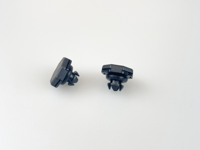
Apakah sistem aliran udara baut MicroVent® dapat dipasang kembali (retrofit) pada inverter surya yang sudah ada?
Memodifikasi inverter surya yang sudah ada dengan komponen aliran udara MicroVent® bolt bergantung pada desain enclosure dan lokasi pemasangan yang tersedia. Banyak inverter modern memiliki desain manajemen termal modular yang memungkinkan pemasangan aliran udara MicroVent® bolt selama perawatan terjadwal atau siklus penggantian komponen. Namun, memodifikasi model inverter lama mungkin memerlukan pembuatan bracket khusus atau modifikasi enclosure, sehingga pemasangan baru menjadi pendekatan yang lebih praktis untuk peralatan yang sudah menua. Konsultasikan dengan produsen inverter Anda atau insinyur sistem termal yang berkualifikasi untuk menilai apakah retrofit aliran udara MicroVent® bolt secara teknis dan ekonomis layak untuk peralatan spesifik Anda.